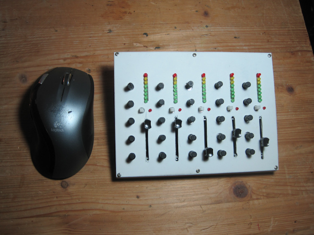
The Mixer 0.1
Mixer 0.1 is my first approach to building a compact universal controller for music programs. It features 5 “channels”, each with one slider, 5 knobs, one button with LED attached and a vu meter. It’s all made to fit on a standard EU pcb of 16x10cm.
More pictures and video on the bottom of this article!
Kicad schematic of the beta and the Arduino patch can be downloaded [here]
Project Goals
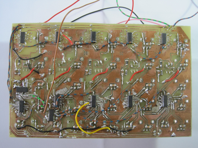
The Dark Side. Quite a few bridges were to be made...
- build a compact mixing controller with controllable vu meters
- gain experience in multiplexing analog inputs
- get more than 7bit controllers for multiple purposes (i.e. f**k MIDI!)
- learn about 14bit midi
- find out about realtime control via serial in duplex mode
- test different controller protocols (14bit MIDI, OSC, Serial, USB HID)
Right now, each slider and knob delivers 10bit readings (0-1023). The readings are communicated to my laptop via an Arduino (serial USB). I’m using Pure Data to then process these readings to (14bit) MIDI to pass them on to programs as Ableton Live and VirtualDJ.
What makes this more interesting are the VU meters. Each LED can be turned on and off remotely, so I can have the level of a deck in VirtualDJ displayed on my mixer as well as the progress of a track or it’s remaining time. The buttons can be used as mute or PFL buttons and so on.
Some tech talk
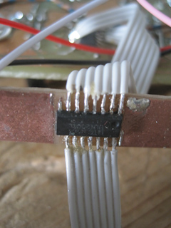
improvised uln2003sfor the LEDs
With 30 analog signals to read (actually 35 because I read the buttons analog, too) and only 5 analog inputs on the Arduino Duemilanove there was plenty of [multiplexing] to do. It was one of the goals of this project for me to learn how it works. In fact, all 35 signals are routed to 1 analog input of the Arduino. For this, I am using a total of 6 [4051] chips. These are controlled by a [4094] register. I also use these registers to control the LEDs of the vu meters. This way I have control access to each individual LED. So, after all, all I am using is the serial communication of the Arduino and one analog pin to read it all, so actually it should be possible to do all this with as little as an [AtTiny].
I considered several ways to control the LEDs. Unfortunately the 4094s outputs don’t provide enough current to drive them so each needs to be added a transistor, for which I used an [ULN2003] darlington array. The array only consisting of only 7 transistors, I decided to couple the two lowermost LEDs together. This way, however small a level there is, you will see the channel is active. Being to lazy to equip each LED with a series resistor, I use a [lm317] voltage regulator to provide 2.5V for all. In my first test runs I experienced some problems which led to my laptops keyboard getting permanently disconnected(!) until I restarted the whole machine. I believe this is due to too much load on the USB port, caused mainly by the LEDs. An external power supply might be needed.
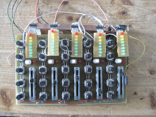
The raw mixer...
An alternative to the above construction would have been to use [lm3914] display drivers. These take an analog voltage to control a LED bar and need no series resistors or other stuff. I would have used the pwm outs of the Arduino to control them. However, it would have given me less control over the LEDs. During some experimenting I also had to find that using pwm on a sensor board can create a considerable amount of noise in the sensor readings.
The whole LED part wasn’t ready in my first pcb design which is why I had to do a lot of hacking and there is no valid design I can provide at this point. I will however provide a Kicad schematic as soon as possible.
Implementation
This part is still in progress as I plan on gaining experience with all kinds of controller protocols.
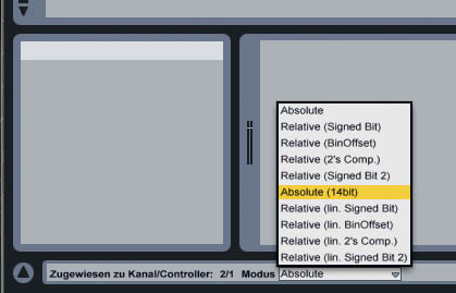
Ableton: choose the type of message you're receiving
Right now I am using the Arduinos native way of communication, the virtual serial USB port, to communicate the readings to and LED states from my laptop. On my laptops side I use [Pure Data] with its [comport] object to handle all the communication. Here, I can convert the incoming 10bit values into whatever format. So far I’ve managed to send 14bit MIDI via a virtual MIDI channel to Ableton Live and to VirtualDJ (only standard MIDI so far :( ) I also managed to get audio levels and track progress displayed of VDJ displayed on my controller. I didn’t feel that much of a delay due to the conversion so far. PDs [comport] object uses a lot of cpu though. It might be interesting to have a different application to do the conversion on a lower level or simply use a whole other method as listed below.
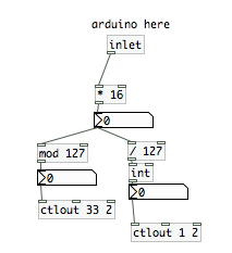
converting a 10bit number into a 14bit MIDI message
Potential future ventures:
- use other Arduino/Controllers to create a USB HID
- send and receive OSC over ethernet directly
- send and receive 14bit MIDI over a hardware MIDI port or as a USB MIDI device
Design considerations
The controllers are populated very dense on this first prototype. I had to cut off the side of the slider knobs to be able to comfortably use the knobs beside them. The knobs position is hard to read since they have no good visible mark. I’ll try some TipEx. Other than that it’s been fun to use so far. What is definitely missing is a few more buttons. Especially DJ programs demand a lot of them, but it would also help to add more functions easily, for example switching between different presets.
Tags: Controller, Electronics