Posts Tagged ‘Controller’

Mixer 0.1

Friday, January 18th, 2013

The Mixer 0.1


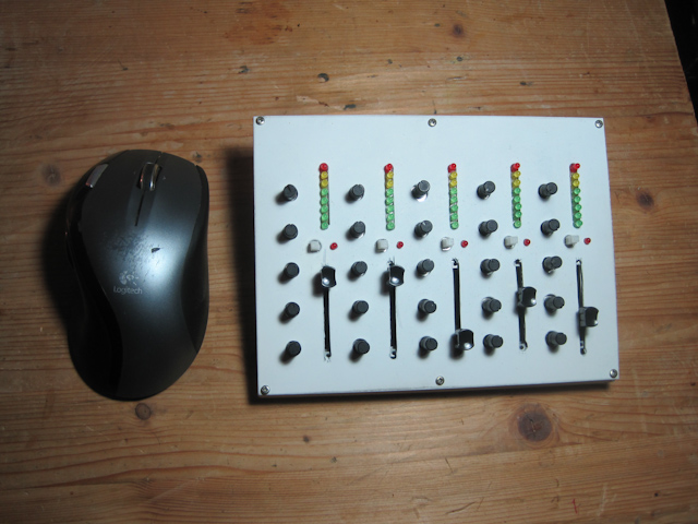
Mixer 0.1 is my first approach to building a compact universal controller for music programs. It features 5 “channels”, each with one slider, 5 knobs, one button with LED attached and a vu meter. It’s all made to fit on a standard EU pcb of 16x10cm.

More pictures and video on the bottom of this article!

Kicad schematic of the beta and the Arduino patch can be downloaded [here]

(more…)

Building Controllers 0.1: Progress

Thursday, November 8th, 2012

I’ve continued on my Mixer project, adding 8 per channel as meters. Currently, each meter circuit consists of a 4094 register attached to a uln2003 transistor array. The idea behind that was that it’s actually possible to control each led individually this way. However, the wiring of these two is pretty space consuming and besides the two chips also each led would need its own series resistor. I tried tow hack myself around that by controlling the leds voltage with pwm from the arduino I use to control and read the mixer. Unfortunately this leads to the pwm leaking into the whole circuit and thus screwing with my fader readings. No good…

For the next version I will use an MC34063 instead. It takes an analog control voltage to light up up to 10 leds and already provides the series resistors inside. Since I will not use the pwm outputs of the arduino for anything else, it seems convenient. The 34063 is a bit pricey though (€1,35).

Apart from all that, the setup worked nicely and I’m looking forward to having it all save and sound in a case to actually start playing with it!

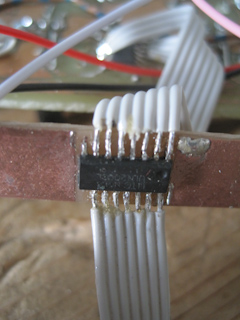
There was no space left on the board for the uln2003s, so they needed to be attached with cables. Sisyphean task...

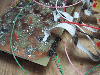
This board is seriously overhacked...

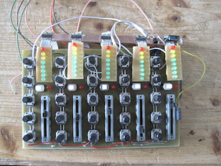
The raw mixer...

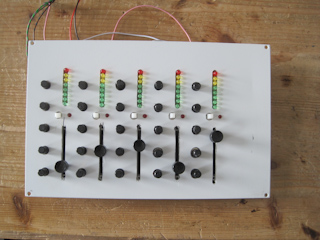
...looks much nicer once you put a lid on it :)

HowTo: 14bit Midi from PD to Ableton Live

Wednesday, October 24th, 2012

Midi sucks. I never understood how people could work with 7bit when it comes to filters or mixing consoles. That’s why I started building my [mixer controller]. Now that it at least works halfway, I started experimenting with its implementation with common computer programs. Luckily, Live has the ability to handle 14bit midi messages, and its easy!

How 14bit midi works

The regular MIDI control message has 7bits, giving you a number between 0 and 127. 14bit messages use two of those, using two corresponding control messages. Looking at the list of [MIDI controller numbers] you can see that numbers 32-63 are “LSB for controllers 0-31”. They provide the 7 higher bits to our value. Controller 1 gives us 2^0 to 2^6, controller 33 will add 2^7 to 2^13. A device or program that uses 14bit midi will expect both messages to be sent together.

I built a small patch in PD that takes an analog signal read by an arduino and converts it to two midi messages, sending a 14bit midi message on channel 2, using controller 1 and 33. Note that the Arduinos analog in uses only 10bit. That’s why we multiply the incoming number with 16, adding 4 bits.
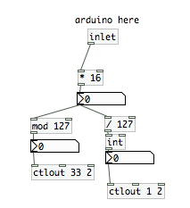
converting a 10bit number into a 14bit MIDI message

The messages are sent via a virtual MIDI port. Here’s a nice tutorial how to set that up on a mac: http://www.johanlooijenga.com/tools/5-apps/12-virtual-ports.html

How to implement 14bit control messages in Ableton

It’s very easy. Activate Abletons MIDI learn function, click on whatever you want to control and turn your knob or use whatever controller you want to implement. Ableton will recognize it. Now look on the bottom of the screen and you’ll see a drop down menu where you can choose the kind of control message Ableton should expect from that controler. Here, you choose “Absolute(14bit)”. And there you go :)
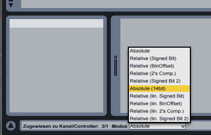
Bottom left: choose the type of message you're receiving

I hope this helps! Let me know if I made a mistake or you didn’t understand something.
Building Controllers 0.1 [updated]

Saturday, September 22nd, 2012

Being a fan of customized user interfaces, I started building me a small mixing desk controller.

The idea is to in the end have a set channel modules that I can stick together and have a mixing desk controller of the size I need. Below you see my first test version that has 5 Channels with 5 potis and one slider and a button with led each (makes 30 potis/sliders in total). They’re connected via the obligatory Arduino, multiplexing one analog in via a combination of 4094 registers and 4051 multiplexers.

As you can see, the first board design needed a considerable amount of hacking. The main feature, a backchannel that feeds 5 vu meters with audio levels, isn’t on the board yet. But so far it works. Stay tuned…


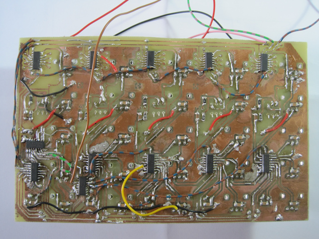
The Dark Side. Quite a few bridges were to be made...


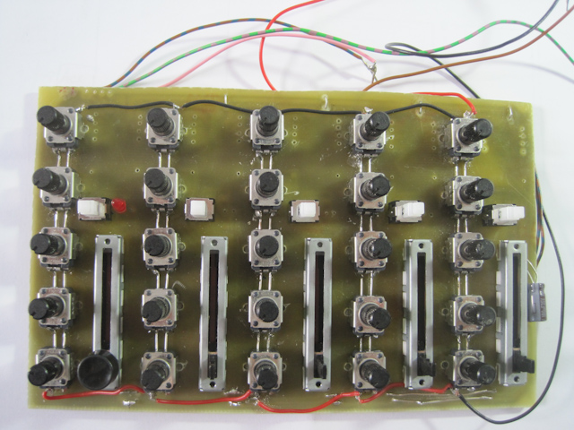
Front view. The pcb is a standard EU (16x10cm). Pretty compact :)

[UPDATE]

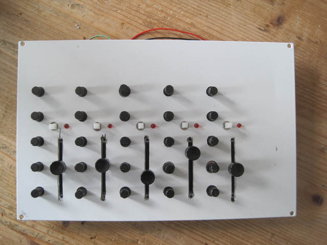
I took a back plate of one of our enclosures at work to build an enclosure for the mixer. I already managed to control PureData and Ableton with it. Next is Virtual DJ. It’s fun for sure!

Now with a little improvised front plate

Arduino Multiplexing / Pure Data Communication

Wednesday, June 13th, 2012

I’m learning a lot of Arduino stuff right now, since I started yet another project. The objective is to create controllers that output 14-Bit MIDI (also known as [NRPN]) or OSC. Reason is mainly that MIDI pisses me off thousandfold. Why the hell are we still stuck to 7 bits when it comes to controlling musical equipment?!?
So I sat down and started designing a sort of mixer controller for use with [Pure Data] that not only controls but also get a visual feedback on sound levels in the form of LED bar graphs. I did a basic layout I will post later. For now it looks like a standard mixing console with

  • 4 channels having
  • 1 Fader
  • 9 knobs (typically 1xGain, 4xEQ, 4xAux)
  • 10 Buttons (Mute, PFL, 4xGroup, 4xPre/Post)
  • 10 LEDs to show button states
  • 1 12 LED bargraph to show audio levels


That is a lot of analog in and output. Considering the amount of free pins on an Arduino, this calls for some serious multiplexing, of which I did first tests in the last days.

Pure Data audio levels on a LED bar graph

I did some first tests connecting two 10LED bar graphs to 3 4093 shift registers. I played audio files in PD, using [env~] to get the dB levels on a scale from one to ten and send them to the Arduino which then conveyed them into the registers. This was a bit tricky since a register only goes to 8 and the two leftover LEDs have to be controlled with the next one. I got it running after a while, though.

Results: I tested several intervals for [env~] and settled for 8000 samples. Everything else made the display too jumpy. The dynamic of the scale is still not satisfactory. That is something that might be solved by software, but the binary output of the 4096 also limits it a lot. While it`s really cheap this way, I might be better off using a D/A converter.

I learned quite some things about serial communication and it’s parsing with the Arduino. I might write a tutorial these days…

Multiplexing analog Inputs with the 4051

To handle the above amount of sliders and potis I’ll have to do multiply it’s analog inputs. The cheapest way I found so far is to use 4051s  (8 ins) or 4067s (16 ins). I salvaged a circuit board from a broken midi keyboard of mine that had 8 sliders and 8 knobs in combination with two 4051s, so I wrote a patch that reads these 16 controllers and reports changes to PD. That worked extremely well. I will post the Arduino program and the circuit here in a while.