Posts Tagged ‘Electronics’

Diskokugel News

Thursday, May 10th, 2012

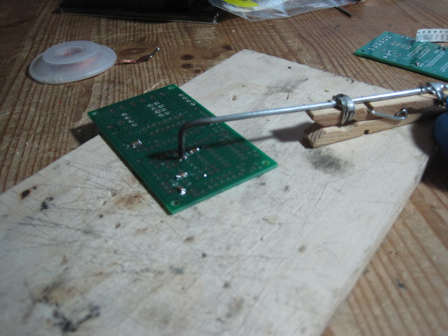
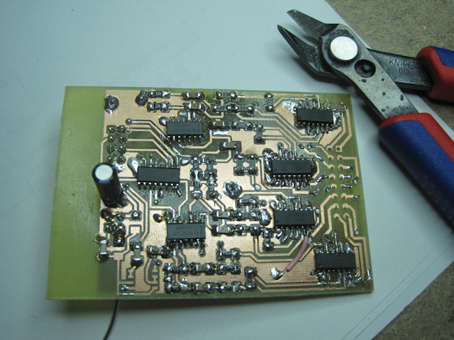
As promised, Christian and I went to testing the new Diskokugel board last weekend. We started by soldering one of the LM4863s he bought on eBay to the new board. Christian had his concerns whether the stuff he bought from Hongkong would actually work :) During the last week I finished soldering most of the parts to board (my first smd project!).

Next week I will test the board as a whole to determine whether the actual delay of 6 months was worth it. If it turns out that the new design doesn’t meet my requirements I will simply go back to the old design and continue there. Progress needs to be made!

testing the lm4863

my first smd board!

CNC me pt. 3 – creating realities

Saturday, December 3rd, 2011

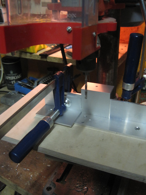
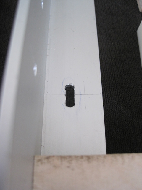
Having at least a plan for the cross table I started working on the parts. I struggled for a while trying to find a place with the means of doing precise cuts and drills into aluminum. In the end I did the cutting in a former workplace of mine and had to do the drilling at [c-base] of which I am a member for about a year now. There I had to cope with a cheap drilling stand. I built me an improvised guide to at least have some precision in one axis. Some holes I had to turn into long holes to be able to adjust to tolerances. Those don’t look so good but I hope it will do.

I found some basic flaws in my design already. I made the mistake of not taking sideway pressure from the drill itself into account. The telescope slides have a sideway tolerance of about 1mm. I will continue anyway, maybe I find a way to correct this by adding guides or the machine will at least give me the means of drilling exact holes and help me build the next one ;)

the drilling guide

a long hole. a crater, rather

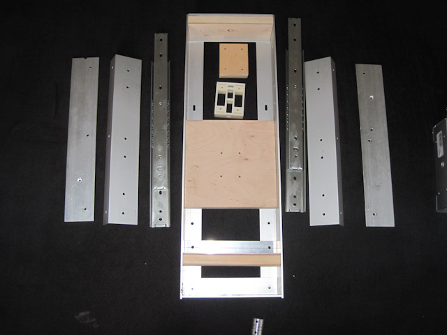
21st of december: all parts drilled

CNC me pt. 2 – Electronics I

Saturday, November 19th, 2011

Searching for a control solution for my CNC mill I found a whole bunch of possibilities. My requirements were these:

  • cheap (why, of course!)
  • USB solution
  • ready PCBs
  • open source if possible

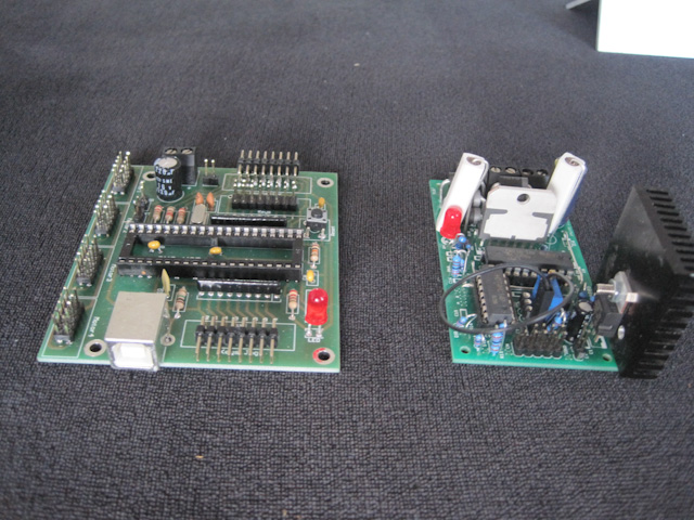
Most CNC configurations still rely on a computers LPT port. This is due to the fact that a program can access this port in realtime as opposed to the USB port, which is buffered. There are several solutions on the web using microcontrollers to execute the code given through the USB port. I went for the one done by [planet cnc] in combination with classic l297/298 motor drivers by [PMinMO]. Both provide ready to use parts, kits and schematics to do your own board designs. I went for the kit solution instead of designing my own boards because I wanted to spend more time on mechanical design. PMinMO provides a truly great documentation with his boards, by the way! I got a PCB and a preconfigured chip from planet cnc. He provides a software with drivers for windows (costs though) that should also work under Parallels and such.

I soldered one driver and the controller board together but haven’t gotten around to do any tests yet…

soldering the smd parts to the driver board

the controller (w/o chip) and one driver, waiting to be tested

CNC me pt.1

Friday, November 18th, 2011

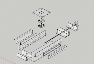
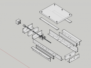
I started making plans for a CNC mill some weeks ago and totally got sucked into it. Here are some pictures of the plans i made with sketchup. More soon…

the bottom axis

the second axis

Trying to make Diskokugel louder

Tuesday, November 1st, 2011

After my first experiences with the [Diskokugel] circuit building [Audioweb] and [AudioSphere] I tried to optimize the circuit for further use. That means I tried to look for a way to get some head room with the volume, since the current design didn’t quite satisfy me volumewise. I discussed the problem with Christian and we did some experiments using a [TDA7053a]. Not only would the TDA make a higher amplification available. Working on 5V instead of +/- 5v, as the transistor circuit works right now, it would have rid us of one power line that has to be transferred into the turning ball via a sliding contact. Also, soldering two chips on the board would have been much faster than soldering those 16 transistors.

The TDA7053 has a DC volume control input, which made us hope that we would simply connect it directly to the 4094 register to switch it on and off, making the 4066 switch obsolete. Unfortunately that didn’t work. The 7053’s offset voltage rises with the applied control voltage, thus producing a crack at the output when raised rapidly. Ultimately we got the thing working by keeping the control voltage at ~0.7V and switching the audio signal on and off with the 4066. However, since in this version all amps are constantly active, I am afraid the whole system would be prone to interferences and the power consumption would be very high. I had a very hard time testing the whole setup. I don’t know if it was my breadboard or whatever, but something started oscillating regularly and there was never a setup tat was save from that or other interferences. Christian told me however that he got something working.

I am not sure how to proceed yet. I think I will stay with the old circuit for now and see how far it takes me. After all, one result of the experiments with the TDA was that a higher volume makes it harder to locate the source of the signal. That would be sort of counter productive. It also shows that there are possibly limits to the use of this whole technique…

A new Gadget 2.0

Wednesday, July 6th, 2011

YEAH!!!!

Behold! I finally upgraded my [bike sound system], adding extra power, a subwoofer and a battery charger for everlasting supply. It doesn’t look as decent as the last one did but it totally rocks. The first test run was a trip to the [Fusion Festival], around 120 kilometers. The dynamo provides enough power to reload the batteries while the system is playing.

I started of with the [TDA7052] 1W amplifier I had already used with the old sound system, only this time I used two, one for bass and one for mid/high frequencies. But the TDA is made for 8Ohm speakers and my bass speaker had 4Ohms and so had the two high/mids in parallel. So I decided to get something bigger. Now I have an [AN7148] delivering 2×2,5W at 12V 4Ohm which is totally sufficient to predominate the occurring head wind and most traffic noise :)

The battery charger was built according to the circuit provided by [forumslader.de] . Documentation is in German only but it’s extraordinary! It’s housing has still to be completed. To be done in time for the Fusion Festival I was a bit in a hurry.

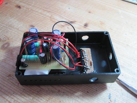
The AN7148 in its housing. Batteries (9xNiMH) sit at the right.

The battery charger

The battery charger


1,2,3 test… (1)

Thursday, May 5th, 2011

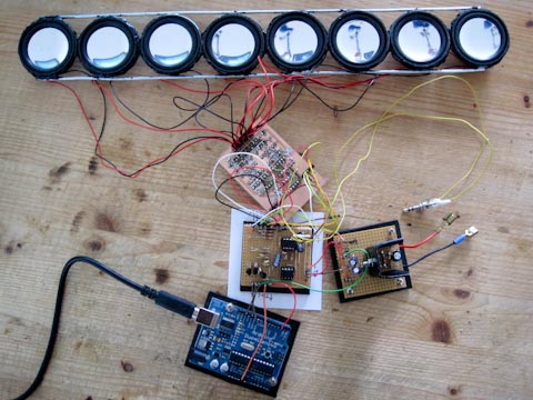
Today I did the first test run with one of the soldered boards and the Arduino. After some adjusting it works but I am not quite satisfied.

On the picture below you can see the setup: 8 speakers, attached to the switching board. Between the switching board and the Arduino is a board that converts the Arduinos signals (0/+5V) to the current level used by the switchboard (+/-5V). This converter board also houses a TL072 for pre-amplification and an LM311 to detect the audio signal’s null phase. This is necessary to prevent the speakers from clicking when switched on and of. And it doesn’t work jet. Why, I’ll have jet to find out…

Speakers, switchboard and Arduino connected. To the right is a voltage divider, converting 12V to +/-6V and GND

Burning a new bootloader into my Arduino Duemilanove [solved]

Wednesday, April 27th, 2011

[UPDATE]

I finally made it happen!!!!

After two days of suffering I found a thorough explanation, how to burn the Arduino bootloader on an Atmega328. This is the solution.
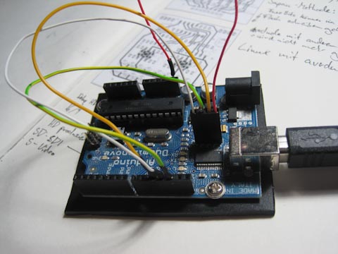
The 'self programming' Arduino

[/UPDATE]

I wanted to start testing the freshly soldered boards for the Diskokugel when I had to discover, I had made a big mistake simply using the Atmega328 of my Arduino in my LED lamp. It turned out to be not quite as simple to replace since the Atmega needs a special bootloader to work in the Arduino board.

There are several ways to burn that bootloader into the chip. The easiest would be having an Arduino and programming it to do it. But since mine was without working chip, I had to look for other solutions. I found one that uses the FT232 on the board to program the Arduino itsself without an AVR writer. However, the solution programmed there is for Windows only. There apparently is a way to do it with a Mac but I wasted a whole day on trying to get it to work. It’s really tiring, installing package after package due to dependencies, having to compile it all, etc. I ended up compiling packages and, when I had finally done that, having forgot what other package I actually wanted to install in the first place.

I’ll try again tomorrow, taking the chip out of the lamp and putting it back into the Arduino. If the Arduino-as-AVRISP works, Ill simply burn me a stash of Arduinos…
Diskokugel Electronics

Thursday, April 21st, 2011

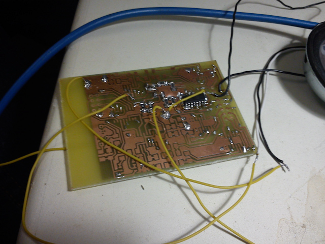
Christian provided me with some sample circuit boards which I assembled the last days.  Christian already had soldered the smd parts in place . Considering my latest clumsy attempts with the icosahedron, this was a wise thing to do. It was still a lot of work to just get the ICs and transistors in place. Once done, I discovered a major flaw in our board design, since the connectors aren’t yet ready to cascade the things. Back to the drafting board…

However, now it’s done and I can run a test with 40 speakers!

Five boards to run tests. The smaller one is the first Christian assembled, the others are ready to be attached to the icosahedron.

A little LED-Lamp

Monday, February 28th, 2011

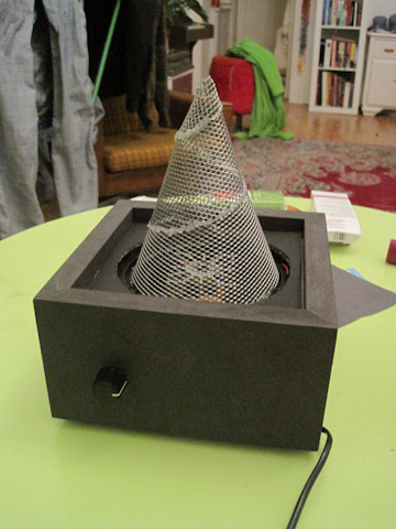
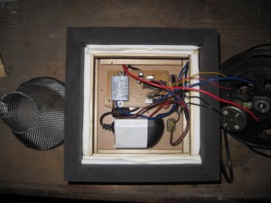
I built a lamp for my girlfriend. It’s quite simple: I took a rotating part of a lamp I broke some time ago (some stupid aquarium simulation), a spare 3 color Cree LED and chicken wire. A little cheesy but quite nice. If you lie on the ground an watch it for some time, the spiral seems to stop and the room rotates instead.


The LED lamp

the knob lets you choose the color or the speed the color changes

color LED lamp

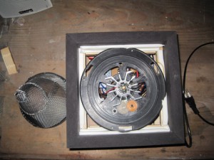
the turning mechanism

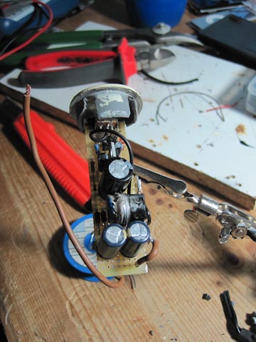
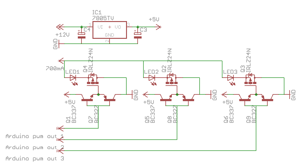
inside: a 12V power supply and a constant current supply for the led, an atmega 328 (arduino)

Of course, the Atmega32-8 is completely oversized for such a project, but it was at hand and programmable via the Arduino. I’m sure the extra constant current supply is also obsolete, but I didn’t get to try otherwise. Comments how to optimize the setup are always appreciated.